Friday 12 April 2013

2D Gaussian blurs or 1D Gaussian blurs

When deciding between a 2D gaussian blur and two 1D gaussian blur passes, it is normally best to go two 1D gaussian blur passes. The reason for this is the difference in efficiency and outcome. Both gaussian do the same function, but differently. The primary difference is what they calculate and not necessarily the exact method as they both take the same approach.

A 2D Gaussian blur takes a particular fragment coordinates and blurs in all directions set by the user. This is nice but can quickly become inefficient. Think about it this way: what if you set your blur square to 5x5? This means your blurring 5^5 pixels, for every pixel on screen. While the end result doesn't look all that bad, it has many weaknesses. 2D Gaussian's are square like by nature and can handle flat, non-circular edges but in terms of anything round, it looks far less impressive. This is where two 1D Gaussians come in handy!


2D Blur, note the blocky edges

Two 1D Gaussian do almost the same thing but instead of sampling a set of 2D coords, it samples two sets of 1D coords. This is very interesting because it is not only more efficient but also looks better. Instead of producing a box type effect, we blur a particular pixel both in the X and Y direction, but not on any sort of angle. This way, we get a nice, smooth circular effect in which looks nice and is much more efficient then the previous style.

Nice and smooth two 1D passes

In conclusion, 1D is both faster and prettier!

The Accumulation buffer

Want to know something evil? It is called the glAccumulation buffer. This will allow you to achieve very basic motion blur, but at the same time it is not the best method of achieving this popular computer graphics effect. Why do we even want motion blur in the first place however? Well, if you swing your arm very fast, your eyes pick up on the movement but it is so fast it appears to be blurred. We can mimic this effect through the use of the glAccumulation buffer or through a shader.


So, what is the glAccumulation buffer exactly? Essentially, instead of doing a gpu based motion blur, the glAccumulation buffer allows us to do a rather simple blur. By placing the accumulation call after all of our primary draws, we can have our motion blur.


glAccum(GL_ACCUM,1.0);
glAccum(GL_RETURN,1.0);
glAccum(GL_MULT,0.45f);

glAccum obtains the R,G,B and A values from the buffer currently selected for reading. GL_RETRUN transfers accumulation buffer values to the color buffer(s) currently selected for writing. GL_MULT multiplies each R,G,B, and A in the accumulation buffer by a value and returns the value to its corresponding accumulation buffer location.


By simply writing those three lines of code after your primary draw, you have basic motion blur. 


Wednesday 10 April 2013

Cross-Hatching Shader

Cross hatching is a fun way of adding cartoon like detail and shading to a scene. It details a scene by adding lines right-angles to create a mesh like appearance. While most often used in hand drawings or paintings, it can be used as a computer graphics effect. In OpenGL, a rather simple shader exists to create a similar kind of scene. All we need is a fragment shader to handle the cross hatching of our scene.

A hand-drawn cross hatching example
For cross hatching, we'll need a 2D texture that will tell us what fragment is being rendered and a luminace value to help determine whether or not our current fragment lies on a particular line. This will also make it easy to draw more lines in areas that need more shading.


uniform sampler2D Texture;
 float lum = length(texture2D(Texture, gl_TexCoord[0].xy).rgb);


First, we will want to draw the enter scene as black. The reason for this is that we'll later be adding in white to create the cross hatching effect.


gl_FragColor = vec4(1.0, 1.0, 1.0, 1.0);

Next is where the fun happens. By determining the strength of a shadow, we can take the mod of the fragment coordinates x and y, add or subtract them together and divide by ten. If it is equivalent to 0, we draw white. We can change the frequency of lines by adding or subtracting to the added value of the added fragment coordinates. Here is an example from learningwebgl.com


/*
    Straight port of code from
    http://learningwebgl.com/blog/?p=2858
*/


void main()
{
    float lum = length(texture2D(Texture, gl_TexCoord[0].xy).rgb);
     
    gl_FragColor = vec4(1.0, 1.0, 1.0, 1.0);
     
    if (lum < 1.00) {
        if (mod(gl_FragCoord.x + gl_FragCoord.y, 10.0) == 0.0) {
            gl_FragColor = vec4(0.0, 0.0, 0.0, 1.0);
        }
    }
     
    if (lum < 0.75) {
        if (mod(gl_FragCoord.x - gl_FragCoord.y, 10.0) == 0.0) {
            gl_FragColor = vec4(0.0, 0.0, 0.0, 1.0);
        }
    }
     
    if (lum < 0.50) {
        if (mod(gl_FragCoord.x + gl_FragCoord.y - 5.0, 10.0) == 0.0) {
            gl_FragColor = vec4(0.0, 0.0, 0.0, 1.0);
        }
    }
     
    if (lum < 0.3) {
        if (mod(gl_FragCoord.x - gl_FragCoord.y - 5.0, 10.0) == 0.0) {
            gl_FragColor = vec4(0.0, 0.0, 0.0, 1.0);
        }
    }
}

   
And a resulting product I made using this exact code:


Monday 8 April 2013

Graphics in Video Game: Ambient Occlusion


Ambient occlusion is the computer graphics effect of approximating how light radiates in real life, especially off what is considered non-reflective surfaces. Ambient occlusion, as the name suggests, is an ambient effect and globally illuminates. The soft appearance created by ambient occlusion is similar to an overcast day.

To calculate ambient occlusion, rays are calculated in every direction from the surface. If a ray collides with another surface, like a wall or another object in the scene, there is no significant change. However if that ray reaches the background, sky, or something else that was set by the programmer, the brightness of that particular surface will increase. As a result, points surrounded by a large amount of objects will appear dark, and objects in the open will be more white. As a final result, the ambient occlusion is then combined with the final textures of the scene to create the effect. The example below illustrates ambient occlusion that was done in Maya and implemented in an OpenGL program.


In this image, ambient occlusion is calculated and stored to a texture. This texture is then combined with the original texture in Photoshop and then added back to the original object. This way it provides realistic lighting to the object in question.

Screen space ambient occlusion

In video games, ambient occlusion, also known as screen space ambient occlusion (SSAO), is a method of calculating ambient occlusion in real-time! The first use of SSAO was for the game Crysis in 2007. Click here for a demonstration of SSAO in Crysis.

SSAO is calculated differently then most ambient occlusion methods simply because of how much potential calculation exists. With SSAO, the depth and surface normal are rendered to a texture in the first pass. In the second pass, a screen-size quad is rendered. In the pixel shader, samples are taken from the neighboring points in the scene. These points are then projected back to screen space to sample the depth by accessing to the texture in first pass. By doing this, we check if the depth sampled at the point is closer or further away than the depth of the sample point itself. The closer the depth sample, the darker the surface as something is covering it.

SSAO in Starcraft 2

Using this method of calculating SSAO could potentially be hundreds of calculations per pixel. With the more calculations done, the better quality the scene will look. To save on computation, some static objects can have a "baked" ambient occlusion texture while others can be constantly updated.

While SSAO is excellent for providing better quality, it has several flaws. One problem with SSAO is that it tends to include artifacts. For example, objects that are outside the screen do not contribute to the occlusion and the amount of occlusion depends on the camera position and viewing angle. Also, the higher the resolution, the more calculations that need to be done. Even small changes in resolution can have big problems.

To reduce artifacts, it is good to blur slightly as it will eliminate any noise left by the SSAO. A Gaussian blur will work for this. Then, upon adding lighting such as Phong, it will create a very nice looking object.


Conclusion

SSAO is an excellent method of calculating realistic lighting in a scene. Since first used in Crysis, it has seen use in many different games. In the future, perhaps we will use better looking and more intense uses of SSAO.


Saturday 23 March 2013

Frame Buffer Objects

In several of my previous posts, Frame Buffer Objects (FBO's) were often discussed and how they are used to a positive effect with such effects as particles, bloom, and shadow mapping. In all of these posts, there was never a great deal of attention spent on FBO's. This week, I will giving a tutorial on FBO's, some code, and a step-by-step on how to make one. Enjoy :)

What is an FBO?

A Frame Buffer Object (FBO) is an extension to OpenGL for doing off-screen rendering. FBO's capture images that would normally be drawn to screen and use these captured images to preform image filters and post processing effects. By using an FBO to assist with post processing effects and different filters, it allows a programmer an easy and efficient way to render out their scene. For example, using an FBO to render out a scene with cel-shading, or shadow mapping. Using Frame Buffer Objects allows programmers to do expensive tasks much easier.

The nature of an FBO is rather simple. Below are the steps of rendering an image to a texture using a Frame Buffer Object.

Steps to rendering an image to a texture

  1. Generate a handle for a framebuffer object and generate handles for a depth render-buffer object and for a texture object. (These will later be attached to the framebuffer object).
  2. Bind the framebuffer object to the context.
  3. Bind the depth render buffer object to the context 
    1. Assign storage attributes to it
    2. Attach it to the framebuffer object
  4. Bind the texture object to the context
    1. Assign storage attributes to it
    2. Assign texture parameters to it.
    3. Attach it to the framebuffer object
  5. Render
  6. Un-bind the framebuffer object from the context.
NOTE: Steps 3 and 4 are interchangable. In the example I show, I binded the texture object first just to show it can be done in a different order.
Coding your very own FBO

Personally, I found coding FBO's to be tricky, but like any programming challenge, it requires time and patience. Don't panic or freak out if you don't get them your first time because that is OK. When creating your FBO, you'll want it to be flexible in its execution. It is important to encapsulate everything in a class for ease of use. So when you're implementing a shader with multiple passes you'll want to set up your FBO's to render to the right spot to avoid any issues. 

NOTE: Any BLUE text is C++ code.

unsigned int CreateFBO(unsigned int numColourTargets, bool useDepth, 
unsigned int *colourTextureListOut, 
unsigned int *depthTextureOut, 
unsigned int width, unsigned int height, 
bool useLinearFiltering, bool useHDR)
{
   // Stuff
}

This unsigned int takes in various arguments  The number of colour targets, whether we are using depth, and so on. The names are fairly self explanatory but let it be known that width and height are for screen size. Let us continue to what exists inside the braces. 

if (!numColourTargets && !useDepth)
return 0;

unsigned int fboHandle;

// generate FBO in graphics memory
glGenFramebuffers(1, &fboHandle);
glBindFramebuffer(GL_FRAMEBUFFER, fboHandle);

Here we state that if we have no colour targets and we're not using depth, return 0. Next, we create our FBO handle as stated in the first step, then we generate the FBO in graphics memory. 

Next we're going to need to create a texture for our colour storage. This particular FBO creator is using Multiple Render Targets. Multiple Render Targets is simple a feature of GPU's that allows the programmable rendering pipeline to render images to multiple render target textures at once. This is very handy for scenes with many textures. 

if (numColourTargets && colourTextureListOut)
{
// texture creation
glGenTextures(numColourTargets, colourTextureListOut);
for ( unsigned int i = 0; i < numColourTargets; ++i )
{

glBindTexture(GL_TEXTURE_2D, colourTextureListOut[i]);
glTexImage2D(GL_TEXTURE_2D, 0, internalFormat, width, height, 0, 
GL_RGBA, internalType, 0);
      // Provide image data such as clamp, min and mag filter

glFramebufferTexture2D(GL_FRAMEBUFFER, (GL_COLOR_ATTACHMENT0 + i), 
GL_TEXTURE_2D, colourTextureListOut[i], 0);
}
}

Now that we have a created texture with different parameters that is bound to a 2d frame buffer, we can move on to create texture for depth storage

if (useDepth && depthTextureOut)
{
                // Generate the texture data
glGenTextures(1, depthTextureOut);
                // Bind it
glBindTexture(GL_TEXTURE_2D, *depthTextureOut);
                // Create a 2D texture
glTexImage2D(GL_TEXTURE_2D, 0, GL_DEPTH_COMPONENT24, width, height, 0, 
GL_DEPTH_COMPONENT, GL_UNSIGNED_INT, 0);
// Include texture paramters such as min and mag filters, clamping.
glFramebufferTexture2D(GL_FRAMEBUFFER, GL_DEPTH_ATTACHMENT, 
GL_TEXTURE_2D, *depthTextureOut, 0);
}

Once you create your texture for depth storage, you can begin wrapping up your FBO creator. Include a simple FBO completion checker to see if there was any errors with the frame buffer status. 

int status = glCheckFramebufferStatus(GL_FRAMEBUFFER);
if (status != GL_FRAMEBUFFER_COMPLETE)
{
printf("\n ERROR: FBO creator failed.");
return 0;
}

As for good practice, disable some things to go back to the original state that your program was at.

glBindTexture(GL_TEXTURE_2D, 0);
glBindFramebuffer(GL_FRAMEBUFFER, 0);
return fboHandle;

Conclusion

That is it! A very simple FBO creator. Remember, when creating your FBO, if you follow the 6 steps to creating a FBO for your OpenGL program, it will certainly ease yourself into it. Remember, simply being patient and going to various different sources is key to writing a successful FBO. Thank you for reading, I hope you enjoyed and learned something!


Source: Bailey, Mike, and Steve Cunningham. Graphics Shaders Theory and Practice Second Edition. New York: CRC Press, 2011. Print.

Sunday 17 March 2013

Bump & Displacement Mapping

For as long as digital environments have been around for, enhancing the appeal of objects has been a goal programmers and artists have striven towards. Many years ago in the world of video games, textures and objects often looked flat and without definition. When creating a digital environment, the style, appeal, and realism is critical when trying to immerse your player within it. These components could range from foliage, structures, characters, cracks in a wall, and more. A popular way to enhance the realism and appeal of objects is through bump mapping and displacement mapping. Both of these techniques are used in computer graphics to enhance realism of textures.

What is bump mapping? 

Bump mapping is a computer graphics method of adding richer detail to an object through changes in the lighting calculations. Jump mapping can make a perfectly round sphere can look like a rocky planet without having any vertices change, just the way the light influences the object. While this method is great for creating realistic walls, floors, and other objects, the drawback is that the objects vertices are not influenced. That jagged rock along the edges is going to look like a perfectly normal sphere. And if that object has a shadow, that shadow will look rounded, instead of jagged. While the not-so-bumpy edges may be a draw back, bump mapping is an excellent way of providing realism to flat objects. In the image below, there is a significant amount of bump mapping in the mountainous regions of the earth.


Once we visually understand the effects of bump mapping, we can begin to understand, as a whole, where we can use it and how. While it would entirely possible to manually influence the vertices of the object, this would be to time consuming and bump mapping can give a more realistic and less expensive effect. It can be used to add definition and realism to different components of a 3D environment to further immerse the user in said environment. Without bump mapping, an object that could look cool would simply look flat and bad.

What is displacement mapping?

While bump mapping is excellent for providing realism to objects, it has drawbacks. Bump mapping does not actually influence the object and this is apparent when analyzing the edges of the bump mapped object. Also, the more bump mapping you use, the more your object looks looks to be bumped mapped and not actually influenced.

Another method to add definition to an object is displacement mapping. Displacement mapping literally moves the vertices of an object to enhance its definition. By displacing the vertices it is possible to achieve highly realistic effects. Instead of an object simply being flat, or a fake bump, it is entirely possible to displace the vertices. This method of achieving realism is becoming more popular, with games often using this to achieve a bumpy wall, or stone floor effect. The image below demonstrates displacement.

The bottom picture being the original image, and the top being the displaced texture.
Note how the above image has crevices and a rugged definition.

What do they share in common?

Displacement and normal mapping use similar methods to achieve their effect. Both begin with an original mesh and a texture (often called a noise map or displacement map) that will alter the original mesh in some way. For bump mapping, because we often try to achieve a rough look, a noise map will be suitable. This will cause roughness in the original mesh. However, for displacement mapping, it will have to be a texture of whatever it is you want to displace.

Can you guess which is bump mapped and which is displacement mapped?

How does bump mapping work?

Bump mapping is very different from displacement mapping. As mentioned before, displacement mapping literally moves the vertices of an original mesh. Bump mapping changes the lighting calculations by use of a texture. This texture can be a noise map, or a specifically designed texture for an object. The modified For this example, I will use a floor to demonstrate how one would go about doing bump mapping.

No bump mapping vs bump mapping
In order to achieve the effect above, a texture is needed. The programmer can specify a normal map that will contain the modified normals for each point of the mesh. To do this though, that requires normal mapping which is similar but different to bump mapping! However, there are fundamental differences between bump mapping and normal mapping. For example:

  • Bump mapping disturbs the existing normals of a model. These original normals are often defined in a 3D modelling program. Normal mapping replaces these normals entirely. 
  • Each colour channel of the normal map an 8-bit bending of the pixel normal on an axis, one axies for each channel: R, G, and B.
  • A normal map uses a both R and G colour channels to distort the original mesh to artists needs. a blank normal map would use the values R: 128 G:128 B:255. The B channel is maxed because it represents flat regions


In the image above, the rocky floor is a mixture of different red, greens and blues. In order to do a normal properly, you must understand that the red and green channels are at 128 initially because it represents a neutral. If you can imagine a scale ranging from 1 to -1 which represents the RGB values (-1 being 0, 0 being 128, and 1 being 255), anything beyond 128, or 0, for the R and G values causes a change or distortion of the surface. 

Knowing this, an artist can play with these different colour values and achieve different levels of bump mapping through playing with the different values. As a ending note, it is best to render your normal maps at a much higher resolution then what the final resolution will be. This will allow the artist to add in extra details and special care to ensure that the final product is exactly what the game designers wish it to be.

How does displacement mapping work?

With displacement mapping a "map" is used to help displace the mesh.   In the example image to the left, the white of the displacement map is used as a strength value to move the vertices of the original mesh. When programming your very own displacement map shader, you wish to do several things:

1.) Read in your object that you wish to displace.
2.) Load in your displacement texture (displacement map)
3.) Wrap your displacement map around your object.
4.) Sample the location of the vertices of the original object in relation to the displacement map.
5.) Whatever color or gray scale value you read in from the sampled locations will be your displacement value.

Using those points in relation to the example image, the displacement map would be applied to the image and the vertex locations read. When the locations of the vertices are seen to be white, and assuming the programming set white to be a positive displacement value, the original mesh will displace accordingly. A programmer though could use different displacement maps for different objectives as well.

For example, to create a jagged stone floor, it would be possible to set a multi-coloured texture to be your displacement map. Let us assume the programmer sets a red value to displace the mesh along the positive Y and blue to displace along the negative Y. The artist would change the original mesh texture to different variations of red and blue so when the displacement texture is sent through the program, you are not only able to create the effect of some stone blocks coming out of the ground, but different levels of depression between the stones.

Use in video games

As per usual: Crysis examples

Bump without displacement

Bump and displacement being best of friends
Conclusion

Both methods of adding detail to an environment have been becoming more and more prevalent as new hardware is released. As better technology come to life, we will see more impressive visuals in video games, as well as an exciting future of high-tech, realistic environments! Whether it be by adding appeal through bump mapping, or definition through displacement mapping, in modern games it is becoming crucial to include these methods of adding detail to enhance the appeal and style of any game. 

Thank you for reading, I hope you enjoyed it! 

Thursday 28 February 2013

Graphics in Video Games: Cel-Shading


Cel-shading, also known as toon shading, is a common method of lighting and shading in computer graphics in order to achieve a hand drawn effect. Cel-shading is often used to mimic a comic book or cartoon feel. This method of shading is becoming more and more popular, especially within the games industry. Cel is a reference to the clear sheet of acetate that are painted on for traditional 2D cartoon drawings, like the original Bugs Bunny show.

What is cel-shading exactly?

Within computer graphics, cel-shading is an increasingly popular way to achieve a unique and fun art style. Some more notable recent games to include cel-shading are Borderlands, Legend of Zelda: Windwaker, and  Team Fortress 2. Cel-shading differs from photo-realistic lighting in that it rather then calculating smooth lighting per pixel, it has lighting that is much more "blocky" in appearance.While the lighting method for diffuse is a more realistic approach as it gives more definition to the character, for cel-shading the character appears more flat but it can complement the games style and design.

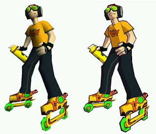
Jet Set Radio - comparing diffuse lighting (left) with cel-shading (right).
So, if cel-shading is used to achieve a cartoon feel, how can I use this to my benefit for game design? How can a programmer take an artists dream and turn it into computer graphics reality? There are many different challenges a programmer must understand before tackling cel-shading. In the image above, the character on the right shows diffuse lighting that gives him depth and definition. However, the character on the right has only 1 definite shadow that gives limited depth. Another distinct feature however is the black edge line surrounding the cel-shaded character. I will discuss how a programmer can over come these challenges and get a cool cel-shaded affect.

Coding cel-shading

As mentioned before, there are two particlar challenges that a coder faces: blocky lighting that looks cartoony and thick black lines that outline the character edges. First, I'll outline how we can generate blocky shading, then move onto edges. (NOTE: In the example image below, this is our base scene in which will describe our scene with NO shading effects. The image has 4 objects loaded from an object loader with attached textures).


To get proper toon shading we need two shaders: a fragment shader and a vertex shader. The vertex shader will transform vertices and send the required variables to the fragment shader for toon shading. Let's get started on some code!

With the vertex shader we'll need two variables to handle the texture coordinates and the normals. Once we declare these variables, we have to get vertex positions, as well as the normals and texture coordinates. This will tell the fragment shader exactly where to draw the toon shadows and apply proper coloring.

Moving on to the fragment shader, there will be a little more programming required here. As before, we'll need the texcoord and normal information, as well as 2 uniform variables: the inputImage and qmap (in this example, the qmap is simple a black to white gradient).

Our qmap
Also, we will need place for where the light will be coming from. In the example I will show you, I chose the light to be in the position of the camera, however, you can really place it wherever you feel is best. Now that the initial variables have been chosen, it is time to start working on the shading component of the scene.

What we first must do in ensure all of our vectors are normalized. Once this is done, we can begin to write our qmap calculation to apply the lighting properly. First, we want to calculate a diffuse. The reason we want to do this is so we can later when calculating the "blocky" value of our shadows.


// Makes sure our normal vector has a length of 1
vec3 n = normalize(normal);

// This is out q-map
float diffuse = max(0.0, dot(n, lightEyeDir));
float blocky = texture2D(qmap, vec2(diffuse, 0.5)).r;


vec3 c = texture2D(inputImage, texcoord).rgb;


With these three lines of code, we calculate our diffuse and take the max of either 0 or the dot product of the normalized vector and the light direction vector. We then send calculate the blocky value which will give us thick strips of shadowed areas, not a smooth gradient like most games. The last line, which will make more sense in a second, takes vector c and gives it the texture2D data of the imputImage and texture coordinates. All that is left is multiplying our blocky value by our c vector to get the desired results.

gl_FragData[0].rgb = c * blocky;

In the end, we get something like this:


Edges!

While the image above gives us the blocky look we want, this hardly looks like the usual cel-shaded effect we are used to seeing. Now it is time to implement the thick black lines that exist around the edges of the objects in order to truly get that old cartoon feel. In order to achieve this, we will need something called the "sobel filter" which is an edge filtering system that is applied to the normal/depth to generate an edge texture. Using the sobel filter, we can generate black texels along the edges of our objects and leave the remainder of the image white (which becomes important later)!

With the sobel filter, we will identify a kernel, similar to Guassian blur, but we will use this kernel to detect if a pixel is at an edge or not. Before we write out sobel filter we be aware we must calculate our edge detection so it picks up on both horizontal and vertical edges. The differences between calculating vertical and horizontal are fundamentally the same, the only difference is the values we use when calculating sum (as seen later).

So, when writing our sobel filter, it will have to take in xy image coords and image data. Next, we will need the pixel size and a sum vector when getting the sum of kernal location and the texture data of the image.

Assuming we are using the kernal:

[   ]
|-1 0 1|
|-2 0 2|
|-1 0 1|
[   ]
we can develop the rest of our shader. (NOTE: depending how much black outline you want you can change these values, but they are fairly sensitive to change. ).


(NOTE: This is for calculating the horizontal edges)

vec2 ps = pixelSize;
vec2 offset[6] = vec2[](vec2(-ps.s, -ps.t), vec2(ps.s, -ps.t),
vec2(-ps.s, 0.0),   vec2(ps.s, 0.0),
vec2(-ps.s, ps.t),  vec2(ps.s, ps.t));

vec3 sum = vec3(0.0);

Once we have this, we can then calculate the sum at every component of the kernel location in relation to the image data.


sum += -1.0 * texture2D(image, offset[0]+texcoord).rgb;
sum +=  1.0 * texture2D(image, offset[1]+texcoord).rgb;
sum += -2.0 * texture2D(image, offset[2]+texcoord).rgb;

sum +=  2.0 * texture2D(image, offset[3]+texcoord).rgb;
sum += -1.0 * texture2D(image, offset[4]+texcoord).rgb;
sum +=  1.0 * texture2D(image, offset[5]+texcoord).rgb;


Lastly, we take the dot product of the sum by the sum and return the value if it is less then 1. Else, we return 0. This will ensure either black or white in our scene. If we wanted to calculate for vertical, we have to treat our kernel slightly different as we are targeting different numbers.

After all that fun code, all that is left is the normals of the two horizontal and vertical sobel filters then we can render out our image. With just edges, our scene will look something like this:

Finishing touches

Currently, we have two images that demonstrate the shading we want with no lines, and lines with no shading. If we take the result of both, and multiply them together, we get something a little like this:


In this image, we have our nice black lines complemented by the fun blocky shading style that we desired. By playing with different variables, such as the sobel kernel or changing the qmap, we can achieve different styles and visuals of our product.

In conclusion

The summarize everything discussed, cel-shading is a computer graphics technique to achieve a cartoon lighting effect. It is characterized by blocky lighting and thick black outlines around objects and characters. For programmers, they will need to know how to implement a proper qmap to get the right amount of shading they want, as well as sobel filters to get exactly the amount of black outline needed for their game.

Thank you for reading, hope you enjoyed it! Rate and comment!


Friday 22 February 2013

Graphics in Video Games: Bloom

When developing a video game, regardless of the platform or if it will be 2D or 3D, the developers must consider how they will utilize the powers of different computer graphics effects. How developers manipulate image data to achieve different effects is absolutely critical for achieving different objectives in game development. An example of a powerful graphics effect is Bloom. Bloom is used to amplify light in a scene, create more realistic effects, or enhance the look and feel of something. This week, I will be discussing bloom in video games, and some GLSL shader code on achieving some bloom effects.

Syndicate: A newer game known for excessive bloom.

What is bloom?


Bloom, also known as glow or bloom light bloom is a computer graphics effect used to amplify light in a scene. As mentioned before, it can be used to enhance realism. The effect of bloom produces 'light bleeding' where bright light will extend onto other parts of the scene. In the image above, you can clearly see the light bleeding onto the play characters gun. This light bleeding effect adds to the illusion of a very bright light.

How can bloom change a game?

Bloom, in most cases, is simply used to enhance the visual appeal of something, whether it be an item, part of the environment, or otherwise. Bloom can also help define a games mood.While some games over-intensify their bloom, a good example of properly used bloom is Far Cry 3.

In Far Cry, the game takes place in a wild, dangerous, yet beautiful jungle across several different islands. In order to achieve different effects of beauty and wonder, as well as cool effects, bloom comes in handy.


In the image above, there are several cases of bloom being used here. Perhaps the first thing in this image someone may notice is the very well done explosion effect. However, using images for particles isn't enough. The light for the particles is being amplified to enhance the explosion so it draws more attention and looks more powerful. Along the outside is a glow to enhance the explosion. Also the interior is white very white. The excessive white we see is called threshold, an important component of bloom. Threshold, in a nutshell, makes colors closer to white more white and colors closer to black more black. This draws contrast and exaggerates (which is also a principle of animation) an effect a programmer is trying to achieve.

The other use of bloom is clearly in the background. The light is so intense that is whites out the background and adds blur as well. This is used to add realism to the scene and try and draw contrast between the mountains and sky. As mentioned with threshold, the mountains are made to be very dark while the sky very white. The light in so intense, you can see the bleeding of color onto the dark mountains.

Now that different uses of bloom in Fay Cry 3 have been discussed, let's move on to some GLSL fun.

How a programmer may code bloom

Seeing bloom and knowing generally how it works is one thing, but how to code it is another entirely. First and foremost, use FBO's to render everything out fast. Second, we want to understand what to use in order to get at least a basic bloom effect. We will need to control the lighting in the scene so we can rely on three different values: luminace, threshold, and middle grey. Middle grey is a controller for the strength of the luminace, allowing us to use different levels of luminace and threshold without going overboard.

Although controlling these would only be a very basic shader there is a problem. Just controlling the different light values is not enough to warrant for a proper bloom effect. Bloom also blurs the surroundings to give it that overbearing effect. For GLSL, we also have to consider down sampling and composite passes. Thus, we need a shader that handles the blur, down sampling, and composite passes.


Gaussian Blur

Gaussian Blur is a method in which to effectively blur in computer graphics. For bloom, it can be used to give the effect of an incredibly bright light that overcomes different parts of the scene, or the scene as a whole. For gaussian blur, we write our code so it is received in the fragment shader. We do this because we want to blur the pixel data itself, and not necessarily the have what is called a "kernel" that is a 3x3 square.

The kernel acts as a 3x3 matrix and our computer will filter the data. In the matrix, it takes the sum of all elements and divides it by the sum. So in the end, the source pixel is replaced by a weighted sum of itself and nearby pixels. This method is called convolution kernel filtering.

While we could take the weighted sum, this is not the only way either. An alternative is to have the kernel weighted stronger towards the center. So each pixel is not weighted on average, but towards the center means a larger number.

GLSL Code


Our original image

After discussing different variables we need to help control bloom, and an overview of Gaussian blur, we can start to work on some code. Using a fragment shader called brightPass, we need the following:

float luminance;
float middleGrey;
float threshold;

This will allow us to control the luminace of our scene or object, the "middleGrey" is used to control grey scale, and the threshold is used to control the white in the scene (as the Far Cry example). Then, we can calculate the lighting for our bloom scene using this shader.

void main()
{
vec3 colour = texture2D(inputImage, gl_TexCoord[0].st).rgb;

colour *= (middleGrey / luminance );
colour *= 1.0 + (colour / (threshold * threshold) );
colour -= 0.5;
colour /=(1.0 + colour);

gl_FragColor.rgb = colour;
}


The image below demonstrates a much more powerful illumination and blurs the scene slightly. This additional brightness, while may be ugly, can be useful in some gaming situations. For example, if the programmer wishes the player to be exposed to a massive amount of light very quickly, this type of high powered bloom can be useful.


However, this is only the brightPass fragment shader and in this, we have a blur effect as well down sampling and composite. For our blur fragment shader, as I mentioned before we need a kernel. However, we also need our image data and pixel size if we want to blur.


uniform sampler2D inputImage;
uniform vec2 pixelSize;


Now, we need a vector representing our box blur. In this vector, we will determine the strength of the blur at a location of x,y (hence vec2 pixelSize) and and output the 3D vector with the 2D blur values.


vec3 colourOut = vec3(0.0);

vec2 offset[9] = vec2[]( // Bottom of the kernal
vec2(-pixelSize.x, -pixelSize.y),
vec2( 0.0, -pixelSize.y),
vec2(+pixelSize.x, -pixelSize.y),

// Middle of the kernal
vec2(-pixelSize.x, 0.0),
vec2( 0.0, 0.0),
vec2(+pixelSize.x, 0.0),

//Top of the kernal
vec2(-pixelSize.x, +pixelSize.y),
vec2( 0.0, +pixelSize.y),
vec2(+pixelSize.x, +pixelSize.y)  );

for( int i = 0; i < 9; i++ )
{
colourOut += texture2D(inputImage, texCoord + offset[i] ).rgb;
}

return ( colourOut / 9.0);

In this, we take the pixel data at a pixel location, add the x and y values together and divide it so that the data at each part of the kernel is the weighted sum and it blurs. This is effectively our Gaussian blur shader. However, we are not done just yet.  We require just one more shader and this is the composite shader that will output for us the color of the scene and the bloom with the added blur. Because it outputs pixel data, it is a fragment shader.

First, we need the input data for the bloom and scene.


uniform sampler2D input_scene;
uniform sampler2D input_bloom;

Once these are declared, we can write our composite main.


vec3 screen(vec3 colour1, vec3 colour2)
{
return ( 1.0- (1.0 - colour1) * (1.0 - colour2) );
}

void main()
{
vec3 colourA = texture2D(input_scene, gl_TexCoord[0].st).rgb;
vec3 colourB = texture2D(input_bloom, gl_TexCoord[0].st).rgb;
gl_FragColor.rgb = screen(colourA, colourB);
}

In the end, this gives us a nice blur effect and a bloomed scene.


Before
After

In conclusion

Bloom in video games is a common method to enhance realism of effects and the environment the player is immersed within by amplifying the scenes lighting. It is a powerful tool that can hinder a game, or enhance the players experience.

I hope this blog taught you a thing or two about basic bloom and how you can implement it. Thank you for reading, don't forget to rate and comment!


Sunday 10 February 2013

Particles in Video Games: Part II


Last week I discussed the basics of particles in video games. This included a basic overview of what particles and particle systems are, different implementations,  and why particles are important in video games. However there are also limitations to what I discussed. CPU rendered particles are greatly inefficient and limited in their ability to look good. This week, I will discuss how to improve upon CPU based rendering by utilizing frame buffer objects (FBO's) and geometry shaders.

The premier way to render any graphics system is through the graphics processing unit, or simply the GPU. The GPU is designed to rapidly build images in a frame buffer to be displayed. GPU's are incredibly common in almost any modern day device such as: mobile phones, personal computers, game consoles, etc. GPU's are very effective at rendering computer graphics because of how it can take blocks of data and process it in parallel. For a particle system, being able to render out blocks of data in a fast and effective manner is critical to producing desirable particles. 

FBO's

The question is, for a particle system, why use FBO's to help render your particles? What is a FBO? A frame buffer object is an extension to OpenGL for doing off-screen rendering. This includes rendering to a texture. By taking what would normally be drawn to screen, it can be used to apply various types of post-processing effects and image filtering. That being said, FBO's are used primarily for post-processing of rendered images (for example bloom, blurring), and composition between different scenes.

Geometry Shaders

Geometry shaders also represent a way to improve your particle system.  A geometry shader, in short, is a GLSL shader that administrates the processing of primitives. In regards to the OpenGL pipeline, it happens after primitive assembly. They can also be used to create new primitives which in turn can be used to help render out textures to quads, a common practice for particle coders. Geometry shaders have several advantages:
  • Unlike vertex shaders, a geometry shader can create new primitives.
  • Can do layered rendering. This means it can render different primitives to different layers in the frame buffer.
  • Excellent for rendering primitives.

How does this help programmers?

A particle programmer would be very wise to maximize the efficiency benefited from FBO's. Rendering to a texture will allow the programmer to create much more realistic effects, while applying different post-processing effects to give them the desired look. This is not the only benefit however, because of the additional speed and parallel rendering, a video game will be able to support many emitters handling many different particle systems that utilize all sorts of different effects. Not only will particles render faster, they can also achieve maximum appeal for the minimal cost.

A geometry shader is an incredibly powerful tool to a programmer. While FBO's assist with rendering, a geometry shader can create new primitives quickly. Many programmers will often render their particles to different primitives such as planes, spheres, or other shapes. This means that their emitter will render quickly because of FBO's and can also create new primitives using geometry shaders

Examples 

Crysis is a good example of a game that utilized geometry shaders in their particle systems.


In this image, the geometry shader could randomly generate the line bursts shooting outwards from the central explosion as well as trail size and intensity. This way, the game can have a unique explosion every time.


For similar reasons as above, the game can enhance player experience by adding in uniqueness to every explosion effect.

In Conclusion

To sum up this two-part blog about particles, they are a great method for achieving a wide array of different effects in video games. They can be used to set a mood in a game and to enhance a players experience. Particle systems, especially good ones, are most certainly a challenge to any proprogrammer. Thank you for reading, comment and rate!


Thursday 31 January 2013

Particles in Video Games: Part I


For our intermediate computer graphics class we have been assigned a various number of challenging homework questions. These questions range from Photoshop manipulations of our game, implementing different types of shaders, and many other game related tasks. Once question however greatly interests me. For it, we have to develop different particle systems. The only trick is that they have to look good! In this two part post, I will be discussing what are particles, what you need to build them, why they are important, and some coding applications.


What is a particle? A particle system?
 
Particles refer to a technique of simulating effects in computer graphics by the use of small sprites or other objects that would otherwise be hard to create. A particle can be represented by using:
  • Points
  • Sprites
  • Different shapes (spheres for example)
With particles you can make any number of different effects such as fire, smoke, fireworks, hair, dust, stars in the night, rain, snow, and just about anything else you can of. In order to achieve these effects one needs a particle system.

A particle system refers to a collection of any number of particles that share attributes.  In video games, they are used to produce all sorts of amazing effects and some games are completely reliant on particles and  particle systems such as Geometry Wars.

An example of particles working with various emitters

Why are they so important?

Particles in video games can be used to achieve many different effects, but they can also be used to enhance or change a gamers experience. For example, a scene littered with fire and random explosions may suggest a war like area, or a gentle snow fall in a forest may give the player a feeling of serenity. They can set the mood, define an experience, make something epic.


With particles you can achieve just about anything. Many games will use them to their advantage to set a mood, such as the example video shows. It demonstrates the increasingly deadly threat of the current areas destruction with randomly explosions and fire.

While mood setting and achieving cool effects are some methods of using particles, they can also be used in a much more practical approach. Particles can be used for bullets, lasers, magical fireballs, and more. Often, in the case of games like Skyrim, when a character casts a magical spell, they are really firing a particle emitter that has collision detection (so we know when it hits an enemy). This type of usage can become a great tool for achieving many different effects for a game.


Coding application of particles


Particles and particle systems share different attributes in the 3D world. When developing a particle system, it is important to understand how each particle works and how they will be effect by particle physics.  Some attributes of a particle would be:
  • Position
  • Velocity
  • Acceleration
  • Life Span
  • Size
  • Color
The list goes on, but these would be amongst the most common you would see. With this, you can fully define an entire list of particles with different attributes to wield at your bidding (evil laugh here). You could implement a fire, water, or smoke style using all of these. Understanding this we can also define a proper particle system to achieve those effects. Particle systems control a group of particles that act randomly but share common attributes. They should be dynamic, not per-determined, changing form and moving over time to get a natural flow in your effect. Some common shared attributes of a particle system would be:
  • Position
  • Number of particles
  • Emission rate
  • Current state (is that tree burning or not?)
  • Particle list (What type of particles are we using)
Typically particles are created from an 'emitter'. While not every single particle has to come from a single emitter, games will often use multiple emitters, if not potentially hundreds. Emitters determine (randomly) the rate, flow, etc., of particles.

Games like Empire: Total War would have taken hundreds
of particle emitters and thousands of particles into consideration.


Particle physics are reliant upon some kind of force. This could be gravity, wind, player influence, anything that may effect a particles acceleration. If we know the acceleration, we can calculate the velocity which then changes the particles position. Once again, this is very useful for the development of various effects.

Effective use of particles is trying to use as little particles as possible to achieve your desired effect. Many games will implement sprites to achieve a fire or smoke effect that uses a fade and color change to give it the proper effect that is needed. You can often see this effect with trees in games where a group of leaves are simply 2D sprites that are effected by the wind in the game. This saves on computation and can be used to make a realistic object in your game.

Sprites are an excellent way of getting a lot for very little. Smoke blooms are often generated by having a very small sprite that grows larger and fades over time to give the proper effect. Sprites were suggested to me by my TA for intermediate computer graphics, and after realizing this, it didn't take long to know just many games use sprites for their particles.

Conclusion

Particles are an excellent way of achieving literally hundreds if not thousands of different goals in video games. From smoke and fire, to mood, or more practical uses like a gun shot, game developers can use them to achieve many different things.

When developing a particle system, you have to take all of these attributes in consideration when creating it. Next week, I will finish off this two part talk about particles about discussing how FBO's and Geometry shaders can be used to improve a basic CPU particle system.

Thanks for reading, I hope you enjoyed it and learned something!